
Room Sound Level Detection with Wireless Microphones
I recently undertook a project with one of my friends for a local university here in Istanbul. The project was basically to implement a detection system in a room to monitor the sound level in that room and display it on a screen. The purpose was to inform the people in the room that they were too loud, given the fact that the room was right next to the library.(This was a rather small university and the library was actually a collection of rooms inside the main building.)
The problem was they informed us a bit late that they wanted to do the project with us so we had approximately 3 weeks to design, prototype, test and deploy the whole system. For this we decided to connect the microphone modules to a Raspberry Pi 3 and hook it up to a monitor, since it is pretty fast to setup a Raspberry.
I wanted to work with ESP modules for a long time but never had a chance to try them, so I thought it would be a good idea to implement the microphones with ESP modules to transmit sound signals through WiFi since the room was quite big and it would be ugly and bulky to use wires to transmit the sound signals from the microphones to the Raspberry Pi.
Hardware
The main design goals was to make the microphone modules small, energy efficient and portable. I first set out to implement the system with a battery for portability but trying to overlap energy efficiency and portability proved to be quite hard, as it turns out the ESP modules tend to have an insatiable hunger for power. Although there is a very useful Deep Sleep mode to considerably decrease the power consumption[1], I didn’t want to implement it because our application needs continuous sound measurement in the room. Because of this the module size was considerably increased due to using relatively high capacity Li-ion batteries, which I scavenged from unused powerbanks.
Luckily, after our first deployment the university wanted to put the microphone modules close to the ceiling - to keep them out of students’ reach - and we were able to plug in our modules to power outlets and designed the second modules according to that and added a generic 5V dc plug. (Yes I know, why do they have power outlets on their ceilings?)
Materials Used for the Microphone Module
- Electret Microphone
- LM386
- LM3940
- ESP8266-12E
- Cap’s and Resistors
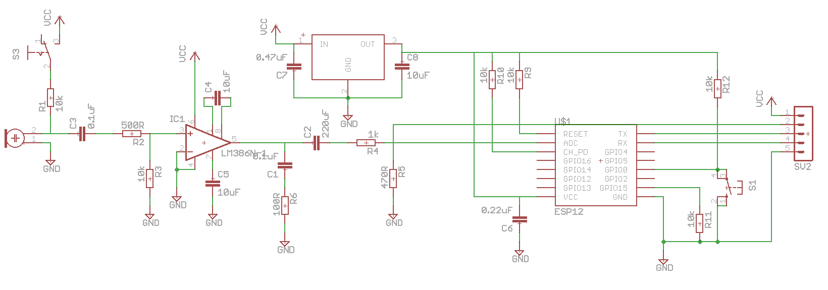
The schematic of the module can be seen in the image below. Basically, LM386 amplifies the sound signals coming from the electret microphone with AG=20 and the LM3940 ensures that the ESP module gets the 3.3V it needs. The LM386 outputs a signal with a mean of 2.5V and can have a peak-to-peak value of 4V in loud environments. Because of this I added a voltage divider to limit the input to the analog input pin of the ESP module to because in some cases, if the input voltage value exceeds 3V the ESP module freaks out[2].
Software
In the transmitting portion of the system, which is the ESP8266 module, software was mostly establishing the WiFi connection and reading/sending the analog pin, but I also added a watchdog timer to prevent the code from crashing to some extent.
#include "Arduino.h"
#include <ESP8266WiFi.h>
#include <Ticker.h>

const char* ssid = "istinye";d
const char* password = "0987654321";
const char* server = "10.234.16.130";
const int port = 10002;
int watchdogCnt = 0;

WiFiClient client;
Ticker secondTick;

void ISRWatchdog()
{
  watchdogCnt++;
  if(watchdogCnt == 60)
  {
      Serial.println("Watchdog boom!");
      ESP.reset();
  }
}

void setup()
{
  Serial.begin(115200);
  secondTick.attach(1,ISRWatchdog);
  Serial.print("Connecting to ");
  Serial.println(ssid);
  WiFi.begin(ssid, password);

  while (WiFi.status() != WL_CONNECTED) {
    delay(500);
    Serial.print(".");
  }
  Serial.println("WiFi connected");

  IPAddress myIP=WiFi.softAPIP();
  Serial.println(myIP);
  delay(1000);

  Serial.println(server);
  Serial.println("connecting...");
  if (client.connect(server, port)) {
    Serial.println("connected");
  } else {
    Serial.println("connection failed");
  }
}

void loop()
{
  watchdogCnt = 0;
  //read the analog pin ADC=A0
  byte resval=analogRead(A0);
  client.write(resval);
  delay(100);
}
As the receiving portion, Raspberry gathers the data from three microphones in data arrays of twenty data point lengths and averages the highest ten of these data points. As it can be seen microphones send analog read values in every 100 milliseconds, thus the decibel value displayed in the monitor is updated in every 2 seconds.
Calculating the dB values
To accurately calculate the dB values we actually need the specifications of the microphone, but because the electret microphones that we used were generic ones with no identification on them, we decided to calculate the relative dB change instead. To achieve this, we calibrated the microphone with a known dB value Vreference and plugged it in with the measured value Vreading into the below equation:
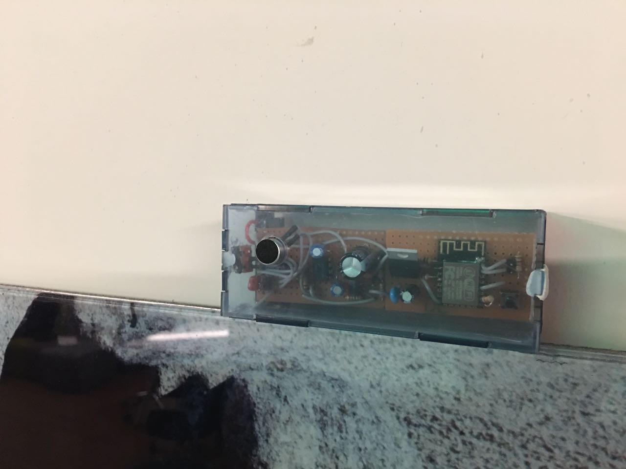
\[dB = 20\log(\frac{V_{reading}}{V_{reference}})\]The deployed Microphone Module MarkI can be seen below. The box was laser cut from PVC and assambled by hand by me and my friend Yigit 3am in the morning. I will probably update this post after I get the PCB and 3D print a sexier looking case for the Microphone Module MarkII.
And here is our baby displaying her skills. The dB values in the gif is pretty high because there was this guy who was very keen on playing the guitar in a student study hall and for some reason nobody seemed fazed by him. A weird school indeed…
All in all, I think we managed to create a decent, working system that was easy to install and use, considering the fact that we had very little time to make it. There are many aspects of the project that can be further improved and I am planning to work on those improvements as I find some free time. First thing I want to look at is the fact that there are three microprocessors that are idle for the most part because they only send data through WiFi. A better algorithm can be implemented to increase the flexibility and the efficiency of the system.
I want to thank my friend Yigit as he was the one who programmed the Raspberry Pi and handled all the commincation with the university staff.